|
Family History
Wines Photography Books |
|
|
TheRagens Wine Tastings
|
In 1996, I was the worldwide industry marketing manager for the engineering and mapping markets at Microsoft Corporation. This was still early in the lifespan for Windows NT in the technical and engineering markets. Object technology which allowed applications to share data and advanced OpenGL graphics technology would ultimately combine with the cost savings of the Windows NT platform in order to change the engineering workstation market. This paper that I published in Computer-Aided Engineering magazine was one of the first efforts to explain this revolution.
Modular CAD: Objects of DesireMatt Ragen
|
|
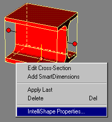
Figure 1 - The Intellishape feature in Trispectives Professional can be used to expose an object’s properties. |
Within the last six to twelve months, a variety of new products have been introduced which treat the design data as individual components or modules in the overall design of new parts. These products promise to change the way that design engineers work. These new products share several things in common. One of the most obvious common attributes is that they use an object-based approach; that is, the product design or the application is built from individual components which each have their own set of properties.
An object, simply speaking, is a piece of data that has a specific set of properties associated with it. Commonly used properties can often refer to the name of the data, creator of the data, the date that the object was created, its size, and other information. An object’s properties can also refer to its unique dimensions, the kind of lighting or illumination, or anything else that is unique to the data. In some circumstances, object properties can include a set of actions that should be taken if the object is activated.
Modular CAD can refer to specific product design data. Any individual component can be a unique object. Consider an I-beam like the one shown in the picture on the right. In a design for a new building, that I-beam may need to be replicated hundreds and hundreds of times in order to complete the overall design. Simply copying a single part like this I-beam should be fairly easy with most modern CAD systems.
However, taking this example one step further, that I-beam has a property that describes its thickness. Suppose the overall building design changes during a project review and the beams need to be thicker to support more weight. Then, it should be possible to change just one copy of the I-beam used in the design. Through links managed by the system, all of the I-beams that are identical should reflect the new thickness. CAD systems that are designed to treat components as objects can do this fairly simply.
This sounds similar to a capability, called associativity, that has been a part of CAD systems for years. What's different about objects? An object model goes far beyond mere associativity. The associativity can be just one of an object's properties that defines its relationship to surrounding objects. A modern object-based CAD system will employ other properties defined by the object model used in the application in order to build new relationships or enable new capabilities.
At the simplest level, modular CAD can treat individual components or parts as design objects. In more complex CAD environments, object-based CAD systems will use other elements that are enabled by the object model to facilitate the design process. The result may be the automation of design methods used consistently within one organization or the result may be the reflection of another engineer's design changes through dynamically linked objects that are used across multiple designs. Some of these extensions will be discussed in the rest of this article.
|
Figure 2 - This AutoCAD drawing is embedded into a Microsoft Word document. |
There are several different object models that are in use today. Within the software community, Microsoft’s OLE specification provides one of the most broadly used implementations. OLE is one of the most commonly used ways to represent and manage data objects across both office productivity and technical applications. For engineers, when used within a design environment, OLE makes it much simpler to handle data objects across different applications.
OLE provides a variety of services that enable data to be shared more easily across different applications. For example, the most common way to incorporate data from other applications into a single data file is to embed it as an object within an OLE Document as shown at right. In this representation, a single OLE document can include embedded objects from a number of other applications. Although the terminology is oriented to word processing, an OLE document can be managed by any kind of a container application that creates OLE objects; AutoCAD R13 and Solidworks 95, in addition to other CAD applications, are examples of container applications.
The embedded object can reside completely within an OLE document. Often, however, the embedded object can include a link to a data file that is located somewhere else on the system or even on a network server. If the object is located somewhere else, the embedded objects can be dynamically updated through the link to the other data. In addition, using a capability that is referred to as OLE Automation, an object can also include a series of steps that should be taken when the object is activated. That is, an application can read and respond to an object’s properties that describe the steps that should be automated. In a design environment, this automation makes it easier to create ‘smart’ objects that may, for example, be able to describe where they should connect to other parts of a design when they are pulled into a design.
Objects make it easier to share data between applications because they introduce a layer of abstraction between the data and the user. Instead of requiring every application to translate data between different formats, objects hold information in their properties that describe how it should be handled by an application. For example, a Microsoft Excel spreadsheet is an OLE object. When that spreadsheet object is embedded within a Microsoft Word document, users can simply click on the spreadsheet object and edit the data using Microsoft Excel commands.
The same analogy holds true in the engineering environment. If you have created a new design for a water pump, for example, then there are certain properties that you would like to be able to store as properties such as the height, width, and depth dimensions, the locations and diameters of the intake and outflow connections, and so on. These properties can then be read using OLE automation when the design is copied into a new OLE document.
For engineers, the overall benefit of all of this object technology is that it results in more efficient use of design tools and, consequently, shorter design cycles by simplifying a portion of the design process.
|
|
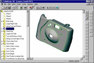
Since product designs are based around a set of properties including dimensions, locations, and shapes, individual design features can also be treated as separate objects. This extensibility helps create a flexible design system. For example, it can help make it easier to change the order in which particular features are created. If features are treated as objects, then they can be easily reordered by dragging the feature to a different location in the design tree. Alternatively, a feature can be copied from one design to another design with a simple cut-and-paste operation. Products like Solidworks 95 and Solid Edge both take this approach in manipulating parts.
The use of objects and OLE to help make products even easier to use is becoming ever more apparent in design products that are priced for broader market opportunities. For example, Trispectives from 3D/Eye offers technologies called IntelliShapes and SmartSnap and Visio Technical from Visio includes the SmartShapes capability. These features work with OLE to make it easy to load a new part object and then, using properties for each object that relate to specific dimensions, align the part along key axis points. For example, a backyard deck uses standard fasteners to connect the support beams to the underlying structure. In the design of a new deck, these features can help ensure that the same kind of fasteners are used and that the position of the individual components is always in the right place.
Object technologies by themselves do not necessarily make design products easier to use. However, the combination of object technology and a well-designed user interface can make products easier to learn. Companies like Intergraph and Solidworks believe that their products can simplify the design process and have introduced benchmarks showing that their products require fewer keystrokes and introduce fewer design errors than other products.
Objects can also be used to do more than just provide a more descriptive way to manage design data. There has been considerable interest by software vendors in moving away from monolithic design applications. Instead, the objective is to build design applications out of independent modules so that specific components can be used, as necessary, to simplify the design process.
Vendors such as Computervision and Matra Datavision are already delivering object-oriented application development systems such as Pelorus or CAS.CADE, respectively. These design systems offer a broad array of software components that can be customized by engineering users. This enables companies to, in essence, build their own unique design systems in order to deliver unique capabilities that they may need in their design process.
Ultimately, because these modular CAD systems share common data structures, these systems can become the foundation for a series of engineering design tools that span a range of requirements. They can be used by the most sophisticated engineers to design the raw systems. They can be customized for less-experienced users in, for example, documentation or support departments that only need to be able to view the design data.
There are many ways to use objects in design environments. One obvious way is in data publishing where vendors collect various designs and specifications from manufacturers into comprehensive libraries and then resell the libraries to end-users. For example, Autodesk offers the PartSpec and MaterialSpec CD‑ROM libraries that contain standard parts specifications from a number of component suppliers. These libraries simplify design processes by making it easier to plug standard parts into new designs rather than having to create the parts from scratch.
The Internet offers a natural next step in this market. On the World Wide Web, after text-based browsing, the data that is mostly transmitted today is comprised of fairly small components - similar to objects. Once parts libraries are created, they can be located on the Internet. Customers can download the part designs from online libraries. This allows parts suppliers to update their designs dynamically or introduce new parts without necessarily needing to distribute paper manuals or brochures.
In using object technology across the Internet, one of the primary methods is to use technology referred to as ActiveX Controls. These controls are small, fast, full-featured OLE components that can be used on the Internet, intranets, and the desktop. ActiveX Controls enable developers to embed a wide variety of software components, such as 2-D or 3-D graphics viewers, animation sequences and product walkthroughs, bill-of-material applets, or other common components directly into hypertext markup language (HTML) pages. ActiveX Controls are already broadly supported by hundreds of software vendors.
A more striking use of online object technology may take place within Intranets rather than on the Internet. Intranets use all of the same technology that are used on the Internet but only span an organization’s internal network and are not open to external users. Beyond data publishing, Intranets may enable a new way of offering product data management (PDM) systems. It is not so far-fetched to envision the creation of an interactive archival system that engineers could use to store and retrieve design data objects. This kind of open system could replace other custom PDM applications.
There are at least three efforts in the CAD industry that are already underway to create standard ways of treating object data between applications. Autodesk has introduced the Industry Foundation Classes, Bentley Systems is building an system called Objective MicroStation, and Intergraph is leading a group of vendors in an effort called OLE for Design and Modeling. These technologies enable object data to be handled consistently when they are activated; in many ways, they may end up replacing standard ways of translating data between different vendors’ proprietary formats.
Object technology and modular CAD systems are mainstream technologies that are being used today. The result is to enable engineers to become more productive. Within a pure design engineering environment, use of technologies like OLE can help streamline typical design tasks. Across a broader organization encompassing both engineering and other departments, object technologies and modular CAD systems help all users share data more effectively.
Acknowledgement: This article was printed with minor revisions in the June 1996 issue of Computer-Aided Engineering Magazine.
© 1996 Microsoft Corporation. All rights reserved.
Return to other papers and articles.
| Face-Off: UNIX versus Windows NT, August 1994 | |
| Real-Time Systems With Microsoft Windows NT Technology Brief, April 1995 | |
| OpenGL 3-D Graphics Technology Brief, August 1995 | |
| Windows NT Workstation in Engineering and Science White Paper, August 1995 |
|

| ||||||||||||||||||||||||||||||||||||||||||||